


Matterport scan to game Engine2986

Frisco, Texas |
Metroplex360 private msg quote post Address this user | |
| Folks, it seems to me that @DannyBasting is creating 'Matterport Studio' as a 3rd party project. I would truly hope that Matterport rallys behind Danny's efforts as I believe that 'Matterport Studio' may be an idea that Matterport released before they had fully developed their vision of what 'Matterport' would be. At this time, 'Matterport Studio' seems to be a niche use product that would not serve the majority of Matterport Users, but that would be an incredible tool for a small percentage of creative and excited users. I'm pretty impressed with Danny's work and want to know more. |
||
| Post 76 • IP flag post | ||

Putten NLD |
DannyBasting private msg quote post Address this user | |
Quote:Originally Posted by Metroplex360 Thanks! |
||
| Post 77 • IP flag post | ||
|
Putten NLD |
DannyBasting private msg quote post Address this user | |
| Just bumping this up for the time being so it won't be archived. Updates are coming but a bit delayed due to a busy schedule. Danny |
||
| Post 78 • IP flag post | ||
 WGAN Forum WGAN ForumFounder and Advisor Atlanta, Georgia |
DanSmigrod private msg quote post Address this user | |
| @DannyBasting Just bumping this up for the time being so it won't be archived. Best, Dan |
||
| Post 79 • IP flag post | ||
|
Putten NLD |
DannyBasting private msg quote post Address this user | |
| Thanks @DanSmigrod, I'll be working on more VR content this week, so I'll post some updates for that shortly. While I've been very occupied lately, I did experiment a little with some different software programs since my last update here (because I can't resist to do so). Thanks to @Jamie who pointed me out to Blender, A software that I've tried years ago, but never really got in to. I've decided to have another go at it though, and I was quite impressed with it. For those of you who don't know, Blender is a free 3D modeling / rendering software. Pretty much the free equivalent of 3DSMax in some way. It's not the easiest to learn though, but once I got a feel for it I really liked it. Anyways.. Below my first ever Blender test: 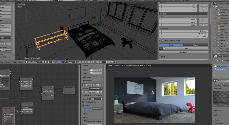 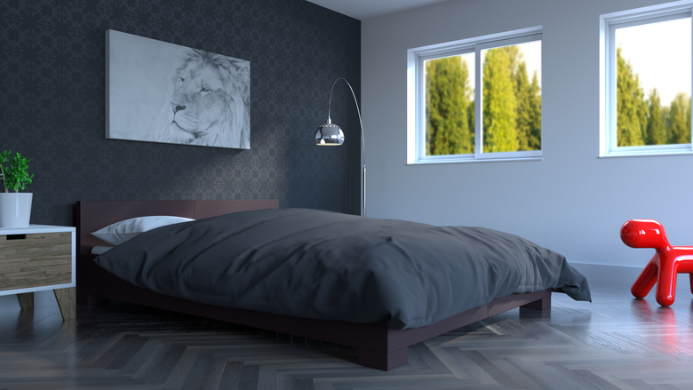 |
||
| Post 80 • IP flag post | ||

|
mori private msg quote post Address this user | |
| Great. MP also posted a WebVR related update. I already made a post here: https://www.wegetaroundnetwork.com/topic/5241/mp-webvr-support-for-oculus-rift--htc-vive/ |
||
| Post 81 • IP flag post | ||

|
AndrewWilliam23 private msg quote post Address this user | |
| Hi Danny, Let me know if you need my help testing stuff you're doing with an Oculus Rift. Just got my rig and controllers last week. Would love to give a hand. | ||
| Post 82 • IP flag post | ||
|
WGAN Forum Founder and Advisor Atlanta, Georgia |
DanSmigrod private msg quote post Address this user | |
| Hi All, WGAN-TV Live at 5 on Thursday (24 August 2017): InventiveCG Founder Danny Basting @DannyBasting will be interviewed by WGAN-TV Guest Co-Host Chris Hickman ( Founder of @Metroplex360 ) Best, Dan |
||
| Post 83 • IP flag post | ||
|
WGAN Forum Founder and Advisor Atlanta, Georgia |
DanSmigrod private msg quote post Address this user | |
| Hi All, Reminder to tune-in ... WGAN-TV Live at 5 (pm ET) today, Thursday, 24 August 2017 for InventiveCG Founder @DannyBasting ... Best, Dan |
||
| Post 84 • IP flag post | ||
|
WGAN Forum Founder and Advisor Atlanta, Georgia |
DanSmigrod private msg quote post Address this user | |
Video: WGAN-TV Live at 5: InventiveCG Founder Danny Basting chats with We Get Around Network Forum Founder Dan Smigrod on Thursday, 24 August 2017 |
||
| Post 85 • IP flag post | ||
|
Putten NLD |
DannyBasting private msg quote post Address this user | |
| Aaaah my accent is terrible! Thanks for having me on your WGAN-TV live stream though! Quote: Originally Posted by AndrewWilliam23 Oculus Rift support is on my to do list, once I implement it I'll let you know |
||
| Post 86 • IP flag post | ||
|
Putten NLD |
DannyBasting private msg quote post Address this user | |
| While long overdue because of a busy schedule, I can finally post an exciting (I think so at least) update in regards to my VR template. I've been working on some new shaders, and I redid the textures of the motion controllers and added some help text in order to make it a bit more user friendly. I also made a material menu where users can touch a material sphere in order to change the flooring for example. Material menu's will soon be properly labeled as well. Big thanks to @Jamie who has been testing and given me great feedback! Quick example recording below: |
||
| Post 87 • IP flag post | ||
|
Putten NLD |
DannyBasting private msg quote post Address this user | |
| I've decided to become more active on social media from now on. So as of yesterday I've created a Twitter account and linked it to my LinkedIn and Facebook page. I'll be posting some additional smaller posts there. So for those of you interested, feel free to follow me on any of those platforms. I will however keep posting the more in depth posts over here On another note: I've added labels to the material menu's in the VR template (see image below) and I did some minor bug fixes. Currently polishing everything up for the Vive version. Once I've done that I'll start working on Oculus Rift support as mentioned before. 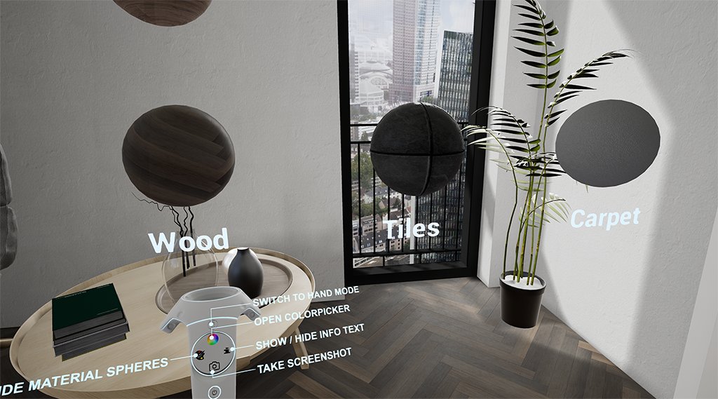 Danny |
||
| Post 88 • IP flag post | ||

|
firoze private msg quote post Address this user | |
| Hi @DannyBasting, i too work on the same kind of stuff you do and use the unreal engine and 3ds max for 3D below is a sample project of mine using Oculus Rift with touch controllers. clickable text if you need my help anytime...I'll be glad to help in anyway possible. good luck |
||
| Post 89 • IP flag post | ||
|
Putten NLD |
DannyBasting private msg quote post Address this user | |
| @firoze thanks for the offer and welcome to the forum! I'll keep that in mind if I am ever short handed. |
||
| Post 90 • IP flag post | ||
|
Putten NLD |
DannyBasting private msg quote post Address this user | |
| On several occasions I found myself to be looking for a particular post in that thread, so that I could redirect people there to help answer reoccurring questions. And while I am happy to help people out and answer questions, I figured it would be more convenient and in everyone’s best interests (including mine), to create a summary of the most vital information spread across the thread. What can be created using an AEC workflow? There are a lot of things that can be created, but I’ve listed the most important items using the flowchart below. 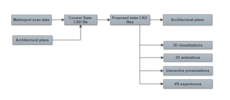 Examples: - Architectural plans  - 3D visualizations 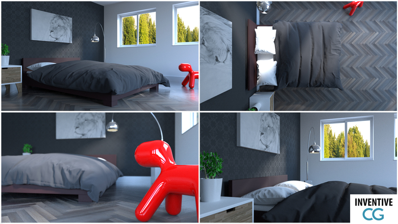 - 3D animations - Interactive presentations - VR experiences As you might have seen in the flowchart, you don’t necessarily need a Matterport scan to create any of the examples above if there are architectural plans available. I do however highly recommend scanning a property, even if plans are available, since it speeds up the overall process. What kind of data do we have? So what kind of data can the Matterport camera provide for us, and how we can use it? First of all, there is the virtual tour, that Matterport is best known for. These virtual tours, have already proved to be an amazing marketing tool for the real estate market, but can also be a valuable tool in the AEC (Architecture, Engineering and Construction) world. If I have it available for one of my projects, I always have it open on a separate monitor, while creating current state CAD files. It’s great to quickly navigate to a specific area to see exactly what the current state looks like on that location. And while that’s great to have while working on a project, the pointcloud data is even more valuable for AEC projects (not to be mistaken with the OBJ file, but more on that later). So what is this pointcloud data exactly? Basically a pointcloud file is nothing but text file with 3 or 6 columns of data and a lot of rows (or lines). The information stored within those columns and rows can be read by 3D applications to give us a visual representation of a 3D object. But how? Like I mentioned each line in the text file has 3 or 6 values worth of information. The first value on each line being the X location of a point in 3D space in relation to the projects origin. The second value being the Y location, and the third being the Z location. These three values give you an exact location in 3d space. 3D Applications can draw a small dot on that specific location, and by combining the millions of lines that an average pointcloud can contain, you’ll get that visual representation of a 3d object or property. What about the last 3 values? These are RGB values, so that each individual point has color data, resulting in a colored pointcloud. A common misconception is that these pointclouds can be edited to create designs straightaway. These files aren’t editable however. (Yes you can edit the values with a text editor, but good luck with that with millions of lines of text) So if they aren’t editable, how is this at all useful? These pointclouds can be used as an underlayment (image1) to create the actual needed geometry by tracing it (image 2 and 3). Doing so is a lot faster and more accurate compared to creating a CAD file based on measurements taken by hand. So no more calculating the exact angle of a wall for example, using up valuable time that can better be spend on other tasks. Image1: 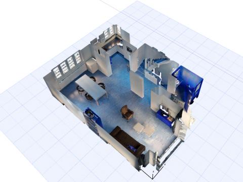 Image2: 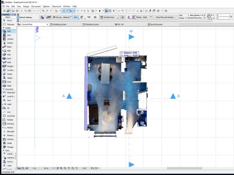 Image3: 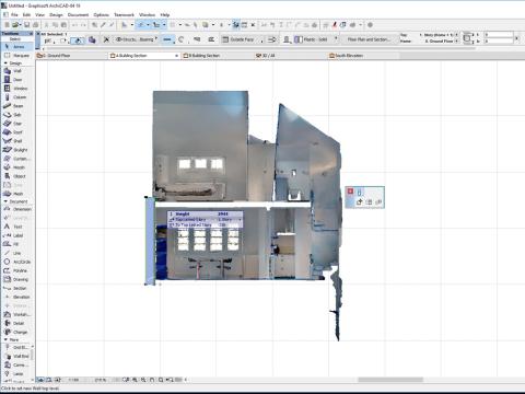 Image4: 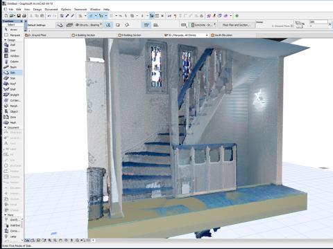 In the end it comes down to this: Using a pointcloud as un underlayment allows for faster current state CAD model generation, saving both time and money. And that’s what it’s all about in the end. Clients are more than happy to pay for a scan if it means they will have to pay less for the end product. With all that out of the way, let’s quickly go over what the Matterport OBJ file is and how it is different from the pointcloud file. While it might not be the most interesting read, I think it’s important to mention since I noticed a lot of people tend to think they are the same thing. Unlike a pointcloud file, an OBJ file is an actual 3d mesh file. The image below helps visualize how a mesh is constructed. You’ve actually got several points in 3d space called vertices (like in a pointcloud), which can be connected using edges. By connecting 3 or more of these vertices, you’ll end up with so called faces, making up the complete 3d model (a cube in case of the example below). 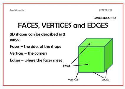 So why go through the trouble of creating own 3d CAD files, while Matterport allows you to download an OBJ file? While these available OBJ files are great for the purpose they are created for (the dollhouse view in Matterport tours), they are close to useless to do some professional 3D-modelling with. Besides having a lot of unnecessary faces on flat surfaces and being a bit messy overall.. the UV maps are close to impossible to work with. UV mapping is the 3D modeling process of projecting a 2D image to a 3D model's surface for texture mapping. I am not trash talking about OBJ files from Matterport, but editing them is just not what they are intended for. Screenshot of a OBJ file: 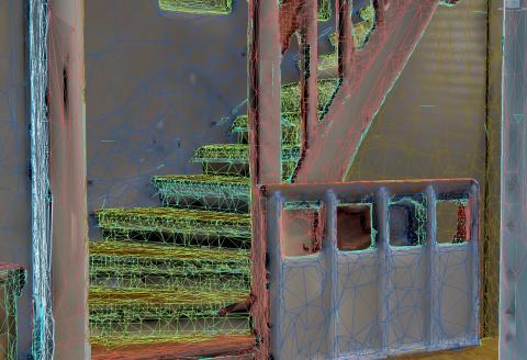 Screenshot of a custom made CAD file of the same property (prior to materializing): 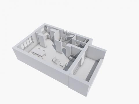 I hope this recap post helps elaborate a bit more about how I utilize the Matterport scan data, and that it answers some of the reoccurring questions that some people have asked. With kind regards, Danny |
||
| Post 91 • IP flag post | ||
 Tosolini TosoliniProductions Bellevue, Washington |
Tosolini private msg quote post Address this user | |
| @dannybasting Thank you for summarizing this useful information. Very well explained! | ||
| Post 92 • IP flag post | ||
|
WGAN Forum Founder and Advisor Atlanta, Georgia |
DanSmigrod private msg quote post Address this user | |
| @DannyBasting Much thanks for sharing. Incredibly helpful for us all. Best Dan |
||
| Post 93 • IP flag post | ||
|
Putten NLD |
DannyBasting private msg quote post Address this user | |
| Thank you @Tosolini and @DanSmigrod, it's good to hear that it was helpful in some way. On another note, I think that in about 4 to 6 weeks I can share some very exciting stuff related to the VR things I've been working on. In the meanwhile I can share some of the additions I've made so far. Since my last update, I've got myself a Vive tracker, which can be implemented in some very cool ways. 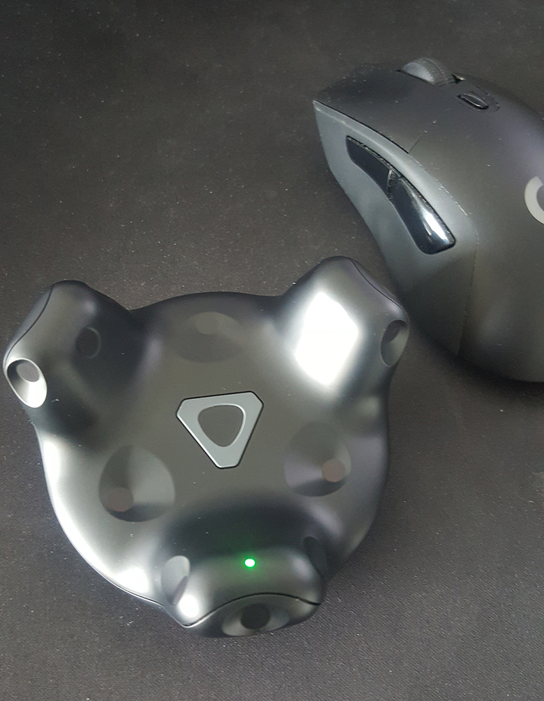 While I am still looking in to new implementations, I already had a ton of fun creating the examples below. Spectator mode: In order for the person in VR to have a sense of where a spectator might be, I've attached a virtual cap and sunglasses to the tracker. That way, the spectator can represented in VR, which doesn't only look pretty cool, it helps with communication as well. 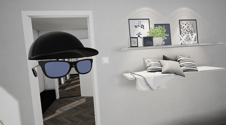 MixeVR camera: Using a green screen, and a physical camera that is trackable (using a Vive tracker), we can create mixedVR recordings. A virtual camera will be attached to the Vive tracker, and aligned with the physical one. After keying out the green screen, the virtual spectator camera can be projected behind the footage of the physical camera. Resulting in footage where you can see the person in VR, standing in the actual virtual world. I've also finally got my hands on an Oculus Rift. While I still need to properly implement it, mapping every button to the correct actions etc, I did get started on the implementation process. 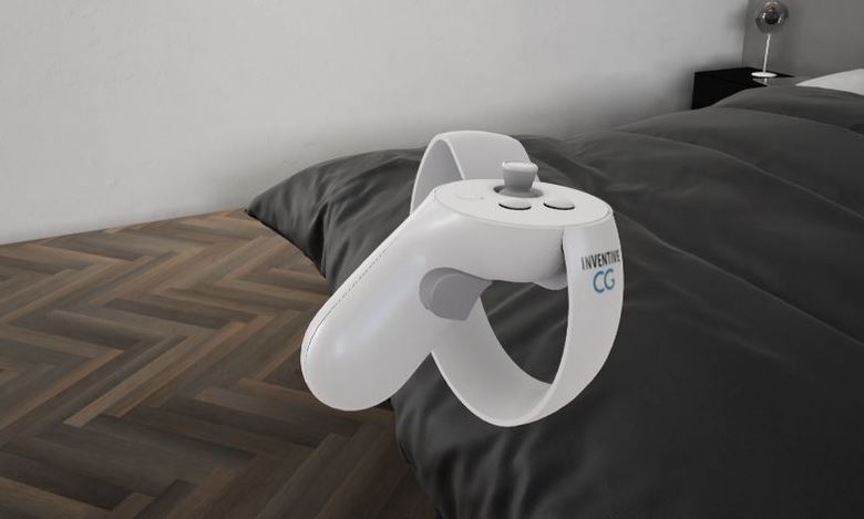 If anyone has any cool idea's on other implementations let me know |
||
| Post 94 • IP flag post | ||
|
Tosolini Productions Bellevue, Washington |
Tosolini private msg quote post Address this user | |
| @dannybasting Super cool! Looking forward to see your work! | ||
| Post 95 • IP flag post | ||
|
|
Mimax_Solutions_Ltd private msg quote post Address this user | |
| Hi all, I've been following this thread for a while and some amazing ideas are coming to life. @dannybasting i know what you are saying about the obj export from Matterport they are a pain but a fantastic base to work from. I've just received a pro 2 but not had chance to use it yet !. It will be primarily for promotional shots for companies we work with, that being said I am very interested in the point cloud / obj capabilities. I have played with sample obj exports, just changing the original balustrade for glass and then extending the floor. this was done quickly as a test but I think the obj isn't bad. once changes have been made to the layout of the obj time could be spent on high quality renders. original glass balustrade extended 1st floor |
||
| Post 96 • IP flag post | ||
|
WGAN Forum Founder and Advisor Atlanta, Georgia |
DanSmigrod private msg quote post Address this user | |
| Hi All, Moving this to the top. Great discussion showing what is possible with the Matterport data. Happy holidays, Dan |
||
| Post 97 • IP flag post | ||
|
|
mori private msg quote post Address this user | |
| Hope I am able to test also more options in 2018 with the MP2 together with the team of VR Base Amsterdam as I am moving now for a longer period to The Hague/Amsterdam. | ||
| Post 98 • IP flag post | ||
|
WGAN Forum Founder and Advisor Atlanta, Georgia |
DanSmigrod private msg quote post Address this user | |
| @DannyBasting Your thoughts on Matterport offering its 3D Showcase SDK to select developers? Dan |
||
| Post 99 • IP flag post | ||
|
Putten NLD |
DannyBasting private msg quote post Address this user | |
| Hey @DanSmigrod, To be honest I didn't have a chance to read up on it to see what this SDK actually offers. I'll read up on it this weekend and come back to you once I have something useful to say Danny |
||
| Post 100 • IP flag post | ||
|
Putten NLD |
DannyBasting private msg quote post Address this user | |
| While I have this page open however, I might as well give you a sneak peak of one of the things I've been working on. I know of the typo that's in the video, but since it's just for testing purposes I didn't bother to change it. Anyway, here is some testing footage of a VR interface I am working on. Also working on a mobile version for GearVR. But the hardware limitations are a pain in the *** I'll report back soon Danny |
||
| Post 101 • IP flag post | ||
|
WGAN Forum Founder and Advisor Atlanta, Georgia |
DanSmigrod private msg quote post Address this user | |
| Hi All, Moving this discussion back to the top ... Best, Dan |
||
| Post 102 • IP flag post | ||
|
WGAN Forum Founder and Advisor Atlanta, Georgia |
DanSmigrod private msg quote post Address this user | |
| @DannyBasting Anything new examples of your work to share? Dan |
||
| Post 103 • IP flag post | ||
|
Putten NLD |
DannyBasting private msg quote post Address this user | |
| Hey @DanSmigrod, I was actually waiting for the greenscreen studio to be completed, so that I can show it of in Mixed Reality, as video doesn't really do it justice.. But here is some footage: Current trailer: Slower paste walk through: Screenshots: 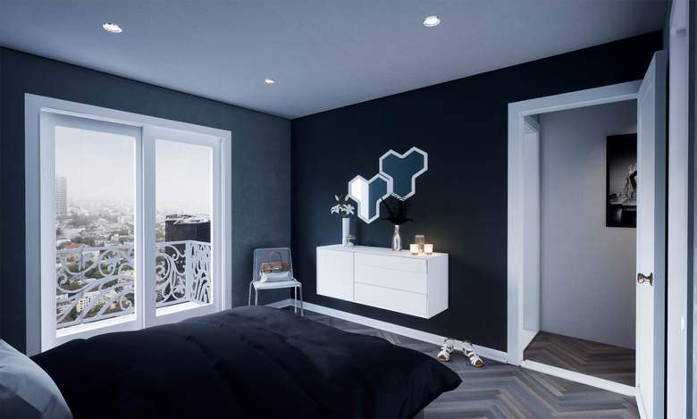 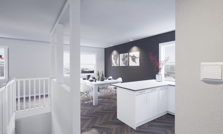 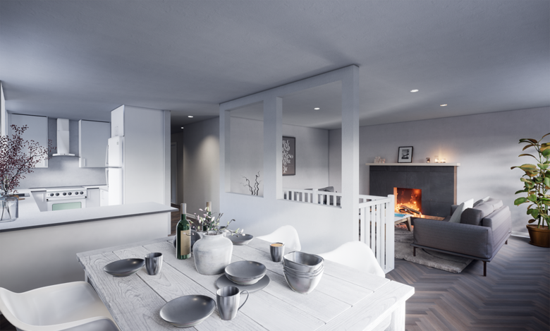 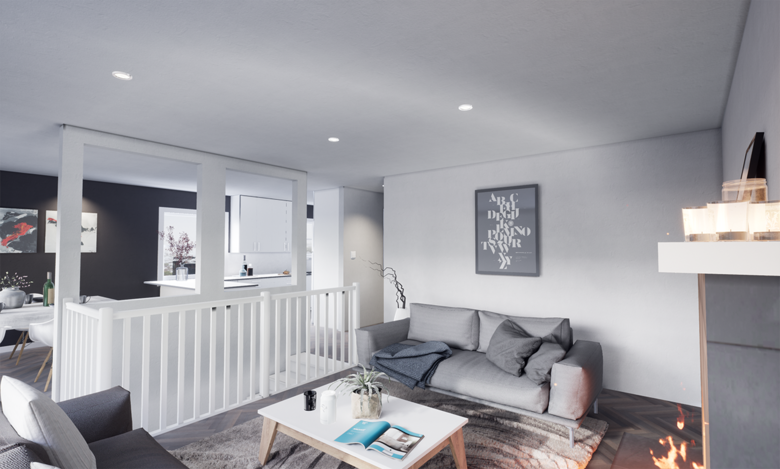 Once the MixedVR setup is ready I will report back |
||
| Post 104 • IP flag post | ||
This topic is archived. Start new topic?