


Build your own BLK2GO16442
Pages:
1
 WGAN Fan WGAN FanClub Member Queensland, Australia |
Wingman private msg quote post Address this user | |
| Ok, it maybe quite stupid to start a project with a robotic rover with purchasing a Lidar but I just could not resist after watching all videos about this product. You can see by its specs and its price it is quite cheap and great in specs and this is a lowest one in their product line. However it is affordable to try and I have just placed an order for Livox Mid-40 I am not sure why it is distributed through DJI website but that's where you go if you decide to buy it. Just in case I want to warn you it will allow you to scan around but it will produce uncolonized point cloud. Not cool but what is great there is a open source project with hardware plans that will allow you to hook a mirrorless camera(they use Sony a6000 in their published plans) along with the LiDAR and you will turn it into a scanner similar to BLK2GO. Here is all hardware plans and apart from making PCBs, buying a few parts and making casing it can be quite cheap if you have a camera already. OPENMMS has a YouTube channel where you can see what you can do on the ground and from a drone with this solution. This video shows how it collects data from the ground And there is one thing that I am going to try first without trying to build OPENMMS system is to see whether I can just create a colorized point cloud from Livox Mid-40 and photos/videos taken during collection. So far I have found this software. But even before I try to use it I will try to do it in Blender 3D as something tells me it can be done in Blender. I am not promising I will show results fast but as soon as I get my Livox Mid-40 I will start trying. |
||
| Post 1 • IP flag post | ||
 WGAN WGAN3rd Party Service Member Beijing |
JuMP private msg quote post Address this user | |
| The FOV of MID-40 is too small, that you may need multiple shoots to cover a full 360 direction. MID-70 may be better. ---------FOV 38.4° Circular (Mid-40) ---------FOV 70.4° Circular (Mid-70) |
||
| Post 2 • IP flag post | ||
|
WGAN Fan Club Member Queensland, Australia |
Wingman private msg quote post Address this user | |
Quote:Originally Posted by JuMP That's ok. It takes 2 sec to get maximum coverage, then I can rotate it. Ideally I want to have a handheld version so I can swipe with it and another one that can sit on a rover and rotates. For that I will try to use it with my two axis Mecha. BTW that OPENMMS project has quite an expensive component in it. Definitely not affordable if it cannot be ignored or replaced with something much cheaper. |
||
| Post 3 • IP flag post | ||
|
WGAN Fan Club Member Queensland, Australia |
Wingman private msg quote post Address this user | |
| I have read today on OPENMMS forum that they are planning to do version 2.0 for hardware and are going to use IMU on Livox Lidar itself instead of hooking it up with Applanix APX-18 GNSS-INS sensor Apparently that sensor is ruining affordability for the whole system to most if not all of users. It costs over $18000. It can be very good at what it is for but you can get a commercial RTK system for 10-15% of APX-18 cost or even cheap RTK DIY boards that cost less than $500-600. Meanwhile I am playing with sample data. Unfortunately there is none available for my model & I am using one from mid-100 What I am going to try first is to capture my own data collected with my Mid-40, then save it as las file using Livox free software(Livox Viewer), then using software called Cloud Compare(also free) create a mesh from it to bring it to Blender and see what I can do with it. So far I am stuck with bringing mesh to Blender as my PC just hangs after I try to import stl file into it. Which is not a big surprise as the data I have comes with 40 million points. |
||
| Post 4 • IP flag post | ||
|
WGAN 3rd Party Service Member Beijing |
JuMP private msg quote post Address this user | |
Maybe you can check this "GoSLAM DS100" for some idea. |
||
| Post 5 • IP flag post | ||
|
WGAN Fan Club Member Queensland, Australia |
Wingman private msg quote post Address this user | |
| There is no english version there. They seem to be using Ouster lidars and as far as I know the cheapest one is about $7000 And there is no camera which simply makes it similar to what you can do with Livox Mid 40 just faster, much more expensive and with everything in your hand. |
||
| Post 6 • IP flag post | ||
|
WGAN Fan Club Member Queensland, Australia |
Wingman private msg quote post Address this user | |
| Found this video with using a Mid-40 on a mechanical rotation base. It seems to be done with 19 rotations stopping for 3 sec for each to get full coverage. Very impressive considering it was done in less than a minute. |
||
| Post 7 • IP flag post | ||
|
WGAN Fan Club Member Queensland, Australia |
Wingman private msg quote post Address this user | |
| BTW, there is no power adapter supplied with the LiDar, only a cable with a plug and contacts. But I am lucky to have a lipo battery and a good charger that has come with a lot of cables/connectors. I have built a power cable already that can power the MID-40 from the lipo battery. BTW it can be powered from a car battery as it accepts voltage from 10 to 16V. LiDar data is coming to a laptop through an ethernet cable and it is great. It can be turned into a wireless connection from the mid-40 to my laptop. I have already purchased a pocket wireless modem. I need to wait till it is delivered as for now I am limited now with a length of my either cable. |
||
| Post 8 • IP flag post | ||
|
|
aerialpixels private msg quote post Address this user | |
| thanks for all these sharing man! | ||
| Post 9 • IP flag post | ||
|
WGAN Fan Club Member Queensland, Australia |
Wingman private msg quote post Address this user | |
| Just one scan about 6 meters from a wall. I have removed point cloud data captured through window. RGB colours shown based on reflectivity of a surface. This is a screenshot from Livox Viewer that is used to capture point cloud data in real time and save it. 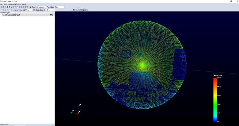 |
||
| Post 10 • IP flag post | ||
|
WGAN Fan Club Member Queensland, Australia |
Wingman private msg quote post Address this user | |
| I have got a pocket router delivered today. The bad thing it does not have a battery so it needs to be powered with an external power source. But from that point it comes with all good things in a setup with MID-40 a) you can power the router from a power bank. It needs 5V and it has a micro USB port for power. b) after a bit of hustle with network IP range and picking up the right router mode I could make it work. Now my lidar is communicating wirelessly with my PC. If you go with the same router(see link below) make sure it is set to "share hotspot" mode with a switch located on a side of the router. It is middle position. As for IP range I honestly tried to use its default 192.168.0.X network but it seems Livox wants 192.168.1.X network range(check Livox manual). So you need just set the router IP to 192.168.1.1 in its admin and it will automatically change DCHP settings for assigning IPs starting from 192.168.1.100 Once I did that the lidar was found by Linox Viewer and started working. Here is the router https://www.tp-link.com/au/home-networking/wifi-router/tl-wr902ac/ Next piece of hardware that is coming is an eternal IMU module that can sync data with Mid-40 through RS485 serial interface. The IMU/GNSS suggested by OPENMMS is $18000 which does not make a project affordable at all. I have found a few in a range of $45 to $600 without GNSS or about $1200 that includes GNSS. I have bought the cheap one on Amazon for $45 with delivery in 2-3 days. Here is a link to it https://www.amazon.com.au/gp/product/B07TJQ77RQ This all is uncharted territory for me and may be a waste of time with a Mid-40 lidar. Their Horizon, Avia and tele-15 are only 2-2.5 time more and come with IMU on board. So if you are not just trying Horizon seems to be a great unit with much bigger FOV BTW, github have a section for Livox SDK and there is already working examples with indoor/outdoor ground mapping and turning a Mid-40 into a Lidar scanner with rotation. I would try Lidar Scanner example even though all examples are for ubuntu and I do not like and do not know linux that well. However lida scanner example using mostly DJI components that are either overpriced or not available in my region(DJI Manifold 2G). Here is their section there https://github.com/Livox-SDK Something tells me that you can just get a ubuntu mini pc to replace DJI Manifold 2G but they also using DJI motor for rotation and I cannot use my mecha instead. |
||
| Post 11 • IP flag post | ||
|
WGAN Fan Club Member Queensland, Australia |
Wingman private msg quote post Address this user | |
| I may try suggesting some extra features to Livox Viewer that can eliminate all this R&D and turn any of their Lidars into rotational scanner right through Livox Viewer. I do not know much about point clouds and not much about their hardware but their Lidars have Extrinsic Calibration feature that allow to apply yaw pitch and roll to a lidar. Once it is done and you start getting data the point cloud is placed according to entered values directly in Livox Viewer. If Livox adds an interface to their viewer for these values for a user to add them manually, set some timers accounting for rotation and time for capturing data it already is turning any of their Lidars into 360 scanners. Just an example, you can have a lidar on a Mecha head set to rotate 360 degree with 20 stops(18 degrees each). The lidar(MID-40) needs 3 seconds to get the maximum coverage in its FOV. Rotating to each position takes say 2 seconds. So in new Viewer interface you can set 20 positions for full 360 coverage, 3 seconds for rotation(just in case ) and 4 seconds for the lidar to be on(capturing data). It starts with 0 degree position so extrinsic Calibration should set yaw to 0 degrees, then within 7 seconds(3+4) you have captured the data in front of the lidar with it is heading as it is placed on the ground. Then Viewer sends a command to the lidar to calibrate its yaw by 18 degrees while Mecha has already turn it physically 18 degrees. Now when Lidar is On again the data will be rotated in the Viewer and placed exactly where it should be relevant to the previous Lidar position and it goes on until it is finished full 360 rotation. It actually works when done manually but there is too much time involved. You need to stop sampling manually and select captured data to go to extrinsic Calibration, then you need to apply yaw by entering a value, click apply and write this yaw value into the Lidar. Then you need another 3 seconds to capture rotated data. And after every position you need to save the data. I have tested with just one rotation and two point clouds are actually come aligned. There may be some tiny misalignment but it is probably due to two factors. I am quite sure Mecha may not be rotating it 18 degrees exactly.. it can be 18.2.. 18.05 while I am entering exactly 18 degrees for yaw in calibration. And second it may suffer from a slight distortion due to parallax error so it is better to now where the laser is emitting from to set a rotation point of a nodal head close to that emitting point. If somebody wants to see what you can get from my experiment with one rotations and changing yaw through Extrinsic Calibration and capturing the second set I am happy to share it on Google Drive. You will need to download CloudCompare to load both point clouds at the same time and see how they are aligned. CloudCompare is free. Now imagine Livox can add an ability to connect an external IMU by simply letting users to specify IMU data format and what COM port Viewer should listen to. You align the IMU on top of the lidar and you can apply not only yaw data but also pitch and roll coming from the specified COM port in real time. What else I have discovered? First I have finally got a meter for lipo batteries. It is kind of bad when you run something from lipo batteries (lidar, robot tank .. etc) but have no idea how much juice left. Now for just $20 I have a display that shows voltage. And another discovery: Not sure how I could not find it for days but there is actually Livox SDK for Windows. it is not just offered through Livox website and you can only get it on github from non related to Livox person. For some reason(I guess wrong version of visual studio) I cannot compile it but I have already asked the guy who is sharing it to help. he offers different compile commands for different version of Visual Studio and he stops at 2017. Mine is fresh 2022 and I guess it may affect while I cannot compile it with Cmake. |
||
| Post 12 • IP flag post | ||
|
WGAN Fan Club Member Queensland, Australia |
Wingman private msg quote post Address this user | |
| BTW, the IMU I have bought has no connection to PC so it is not even possible to calibrate unless you buy a RS485 to USB adapter which cost about $30. So I have got another version of the IMU from the same manufacturer that comes with bluetooth build it. It is less than $60 AUD If I cannot connect it up with Lidar I can put it on a robot tank to get yaw, pitch and roll. There is may be also possible to calculate distance traveled with the IMU data. Here is a very interesting application for IMUs |
||
| Post 13 • IP flag post | ||
|
|
aerialpixels private msg quote post Address this user | |
| computer art |
||
| Post 14 • IP flag post | ||
|
WGAN Fan Club Member Queensland, Australia |
Wingman private msg quote post Address this user | |
| I have a good news. I could install Livox SDK on windows pc. When I run Livox examples that comes with the SDK they all work-connecting to my lidar, collecting data and even saving it in a file. I will try to learn how to work with lidars and point clouds but as a plan B I can hire c++ programmer with an expertise in hardware and specifically in Lidars and point clouds in order to write a windows app to turn Livox lidars in rotational Lidar scanners. If it is all good I may be able to turn it into paid but affordable app for Windows. How much do you think others will be ready to pay for it assuming the cost of a cheapest Livox Lidar(Mid-40) is only $600 and apart from a rotator only a lipo battery($50-60), a pocket wireless modem($50) and a cable($5-10) needed to turn it into a 360 degree stationary lidar scanner? This will only cover vertical FOV of the lidar(38 degree) because itis going to be one row rotation. At stage 2 I am thinking of adding support for an affordable IMU module($30-500) which data my app will read through the same com port the module connected to and applying it to collected points. This can actually be extended by not just applying yaw angle from IMU but also pitch which should allow to use a small FOV lidar but capture more than 38 degrees vertically. It means you can do more than one row tilting lidar on two axis motorised head. The head does not even need to have connection to the app as the IMU module will be sitting on top of the lidar and measuring both yaw and pitch angles passing both to lidar to calibrate captured data. For Avia and Horizon modules it is possible that no external IMU will be required as the app will read IMU data from the module built in these two models. At stage 3 we can add walking mapping mode(the same what BLK2GO does) And as a last stage we can add a camera support to make a colorised from its photo point cloud. And at any stage starting from 3 we can try to add GNSS support. BTW, if you are a windows only programmer and do not mind to invest in the cheapest one(mid-40) to play and write an app you can see details on how to compile SDK on Windows on the link at the end . It took me two days with a lot of faults. However I think the reasons were I was using a new version of Visual Studio 2022 while Livox instructions in their Readme.md end with 2019 version. And the second I was forgetting to turn off Firewall. Once I rolled back to Visual Studio 2019 and turned off firewall I had 0 problems with compiling SDK. https://github.com/Livox-SDK/ |
||
| Post 15 • IP flag post | ||
|
WGAN Fan Club Member Queensland, Australia |
Wingman private msg quote post Address this user | |
| I am communicating to KITWARE developing team who has developed ParaView and another app called LidarView. The last one allows to use lidars for mapping via SLAM. They do not yet support Livox LiDARs and I am hoping they can add them as supported devices. ParaView & LidarView are free and Windows based apps. |
||
| Post 16 • IP flag post | ||
|
|
aerialpixels private msg quote post Address this user | |
| @Wingman hows the project coming along? | ||
| Post 17 • IP flag post | ||
|
WGAN Fan Club Member Queensland, Australia |
Wingman private msg quote post Address this user | |
| no progress so far but I am waiting for a reply from Paraview developers who seem to be interested to implement Livox lidars into their free LidarView app for Windows. | ||
| Post 18 • IP flag post | ||
Pages:
1This topic is archived. Start new topic?