


Video: GUIDE Master Class Webinar: Drafting Standards and Floor Plans16001
Pages:
1
 WGAN Forum WGAN ForumFounder and Advisor Atlanta, Georgia |
DanSmigrod private msg quote post Address this user | |
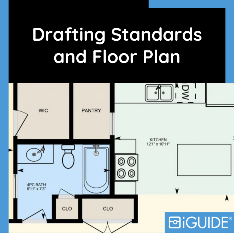 Image courtesy of iGUIDE Video: GUIDE 3D Tours Drafting Standards - Masterclass | Video courtesy of iGUIDE YouTube Channel | 16 November 2021 --  iGUIDE --- Transcript (video above) Evan Maxwell: [00:00:00] - Hello everyone. I hope you can hear me. I'm not the usual face you see on this and that's for a reason. Partly I'm not that familiar with Zoom. Right off the bat, I'm going to ask you to be patient with me while I struggle through this. [00:00:30] Actually, first before I say that, if you have any questions, you can ask those in the Q&A section. By the time I'm done with what I have to say, I'll get to those at the end. You can ask those there. Today, what we're talking about [00:01:00] is the iGUIDE Drafting Standards & Policies. Now let me just get my notes. For the purpose of this [00:01:30] discussion, we're going to have a focus on the drafting standards specifically. Now, iGUIDE is unique and this document in particular is unique in that it necessarily includes a mixture of both drafting standards, so how things are actually shown on the floor plan, and measurement standards. [00:02:00] That's because your iGUIDE, the measurements, the dimensions, the floor area totals, those are all automatically determined or automatically calculated, generated based on the drafted floor plan. [00:02:30] The iGUIDE drafting team, they're also trained to include and exclude certain areas based on various criteria as part of the process. That's prescribed in such measurement standards as RMS and ANSI Z765, which the iGUIDE drafting standards and policies are largely based on which it states [00:03:00] right here. Like I said, the iGUIDE drafting standards and policies is necessarily a mixture of both drafting and measurements standards. That's just naturally how this document came to be since the iGUIDE drafting team. Though their process, we refer to it casually as drafting, is not specifically or not exclusively [00:03:30] drafting. There's a lot more that goes into creating your archives than just the drafting or just the measuring. It's a unique combination of both. To put it simply, the drafting standards, part of this, in other words, how a space is drawn, and the measurement standards or how a space is measured? Today, we're going to focus on how the spaces are drawn. We'll skip some parts of this document which [00:04:00] deal only with when to include and exclude spaces. For example, so you might be wondering actually where I got this. This is available to download for any of your iGUIDE service providers on the portal under Supports and the Planetary Drafting Policies and Measurement [00:04:30] Standards. Here as well as some other RMS info. That's where I got that. Now, I suppose we just get into it. I brought up just one of our sample iGUIDEs for example just so we can refer to it throughout the discussion. [00:05:00] Depending on what exactly all those available here, I'll switch to a different one that I have. Another one opens in our drafting software for when we get to that as well. I'll try and bring the visuals into this discussion as much as I can. First off, we'll just go point-by-point, follow logically through the document. [00:05:30] First point here is on floor areas. That's on page 3, part 1, so iGUIDE floor plans are drafted to be a schematic representation of the home. They're not meant to be architectural floor plans detailing every aspect of the home. What does that mean? Well, that means that iGUIDEs are designed for a specific purpose in [00:06:00] that they're used to act as a map, an interactive experience to document and show the use of the space primarily. Not so much as a detailed look at every particular [00:06:30] finish or type of wall or window or different wall construction, it's primarily for the use of the space in that iGUIDEs are largely used for real estate measurements. When you get an iGUIDE, [00:07:00] you're not getting a floor plan which looks like many of these, which has, for example, very detailed measurements that may have call-outs that direct your attention to a different page which might have a wall section rather I should say. It might show details like different hatching or shading for different [00:07:30] types of wall construction. An architectural floor plan would really get into the details of all these things. It would use this to distinguish different wall construction, exact door and windows styles as you're familiar with. iGuides, you'll see a limited selection of types of doors for example. [00:08:00] Here you can see we have a pocket door here. In another area of the home, front door we'll have your standard swinging door, and then in other areas we'll have things like just the door opening, if you will. Now, on an architectural plan or otherwise, you might get into even more detail. It might be a call out or [00:08:30] the object itself on the floor plan might be more detailed. But you might distinguish this door with a side light and the glass in the middle of the door. You might distinguish that from your standard bedroom door, which is just solid all the way through. That's what we do with those. You can find that type of door which I'm seeing here. [00:09:00] Yeah. I'll refer back to my notes. Architectural plans, they utilize a greater level of detail on the floor plan in order to convey information about a property. iGUIDEs utilize both floor plans and images. This level of detail on an iGUIDE floor plan is not necessarily as important. In other words, we can fit more information in an iGUIDE using both the images in combination with the floor plan. We're not limited to just what's shown on the page. [00:09:30] Furthermore, adequately surveying and drafting this much information would also require significantly more time and effort of both yourself and iGUIDE camera operator and the drafting team. That could mean more time on site and more time assessing. That's our approach on that. Back to the drafting standard. Floor areas, three, [00:10:00] we're talking about perimeter wall thickness here, the exterior area. I remember we're talking about how things are shown, not necessarily the measurements or which faces are excluded or included with talking about how it show on the floor plan, how it's drawn. We'll talk about how perimeter wall thickness that you enter translates [00:10:30] to the drafted floor plan. As some of you will be familiar with, the perimeter wall thickness shown on the floor plan is often, but not always, the same as what you record in survey or stitch. You-all know that perimeter wall thicknesses on any given floor can vary greatly in reality and on [00:11:00] the floor plan. For iGUIDE Method Of Measurement, we measure the inside, the paint to paint what's inside a property. There is a certain amount of assumption what goes on with what would be the outer surface of the perimeter wall [00:11:30] of any given floor. iGUIDE Method Of Measurement only requiring indoor scans accounts for this variability, and that influences the drafting standards in that way. Naturally, iGUIDE perimeter walls are drafted with a balanced approach. Where you'll typically see aesthetic uniformity on the outer [00:12:00] face of a perimeter wall. I'm talking about this side, and you'll see a varied thickness on the inside, wherever that occurs. Since obviously we have access to that information and we can see that. I think you see a bit of that and the corner on the second floor. Something like that, we have a little detail there. Let me just get back to the second floor again. [00:12:30] You'll see that this bit of the wall is actually a bit thicker here as well. But you'll also notice is that all around the perimeter is uniform, and that's simply put, that's just because we can't see that outside. For iGUIDE method of measurement, let me just see if I can [00:13:00] bring that up. You'll know that you actually have the ability to change the perimeter wall thickness value on the portal, and that's because it doesn't rely at all on the thickness of the wall drawn on the floor plan. It actually uses the value that you enter based on the drafted perimeter wall [00:13:30] length. To account for variability, you could do what we call a weighted average of any varying perimeter walls thicknesses, you could enter that as the value and that would be used in the calculation. When I said at the beginning that the perimeter [00:14:00] wall thickness is often but not always, the same as what you record in survey and stitch, that's what we mean. Hopefully that makes sense, and I can revisit that if anybody wants some more clarification on that. But basically, where the measurements on the floor plan effectively end is on the inside face of that perimeter wall. Anything on the outside is a guess and so that's not used in the calculation. [00:14:30] That's where the perimeter wall thickness that you enter is used on the exterior area. It uses that perimeter wall length and that perimeter wall thickness to generate that exterior area. Moving on at this point, we'll go to number seven for proper area reporting floors [00:15:00] belonging to separate buildings must be assigned to a new building in stitch. It's the operator's responsibility to assign florist the appropriate building using stitch. Some of you will be aware that multiple buildings are not to be drafted as part of the same floor plan. That's for a few reasons. In our software, [00:15:30] the draft software, which the drafting team use, which I am just showing here on screen now if you haven't seen that before and we'll get into that in a minute. The automated area calculations that we do in that software require buildings to be drafted separately. The calculations are done on a per floor and per [00:16:00] building basis. This particular property doesn't have multiple buildings, it just has multiple forest part of one building. What you wouldn't see is, for example, if this building had like a workshop out in the backyard, you would see that in the drop-down list and classified [00:16:30] as a separate building. Because if that building were featured on the same floor plan, that would affect the area totals of this main floor of this building as well. They would essentially be considered the same building even though they're visibly separate. That's just how the software needs to run its calculations. [00:17:00] Secondly, iGUIDE floor plans are floor plans by design. Emphasis on floor. They're not site plans. If any of you aren't familiar with what a site plan is, just so I can help you visualize that. A site plan is exactly those plans where you would feature multiple buildings like this. When I say that iGUIDE floor plans, [00:17:30] are floor plans. They are exactly that, they're designed to be floor plans, they're an indoor camera, indoor mapping system, and so they're optimized for indoor use, and it can actually be difficult to position multiple buildings reliably on the same plan relative to each other due to these technical limitations, like getting adequate scan data. If this [00:18:00] building was on an angle to the building which they often are, and at some distance it would be difficult to feature that on the same plan. Not only that, but the iGUIDE viewer, as you're aware, is not yet optimized for varying floor heights on the same level. As we can see here, just so I can zoom in here, there's these appearing down here on the floor and then you can just [00:18:30] barely see that through the table out there. The iGUIDE viewer is not yet optimized for varying floor heights on the same level, and uneven surfaces like that are ubiquitous of the outdoor environment. That's why that's not done in your iGUIDEs. Moving on. Once again, we'll go to [00:19:00] floor areas. Floor areas, algorithms must have a minimum floor to ceiling height of seven feet, ramps with slope ceilings I measured at a height of five feet only if the ceiling height exceeds seven feet and at least one location. That comes from [00:19:30] RMS. This is also mentioned in rooms without a perpendicular walls, Part 36. Basically it says a similar thing, it says iGUIDE cameras must be leveled and a tripartite must be adjusted, so a laser scanner height above the floor is at five feet. These are slightly different we can get into the differences there. If I scroll back up [00:20:00] to number 8, the bounding walls of low height rooms are drawn where the wall meets the floor. I'll open draft to show you what I'm talking about there. I'll just expand my view so you can see the image. Here we've got a family room on an upper level [00:20:30] which has a slope ceiling, and you'll see that the scan was taken at about 45 feet above the floor level. Sloped walls and ceilings complicate things for us here because drafting relies heavily on the walls being perpendicular, in other words, at a 90 degree angle [00:21:00] to the floor. Slope, ceilings and walls, they complicate things for us, but it's not impossible under the right circumstances. We can see here, I was saying, what this blue line represents is where this height at which the scan was taken, so this is the laser data. Cuts the room in two-dimensions here in this straight line all around. [00:21:30] The actual wall where the floor meets the wall. This corner, this edge here, at a distance behind where this laser actually hits. We actually have some pretty sophisticated tools to help us identify where that wall can be drafted as long as we also have [00:22:00] sufficient view of that area. I'm not going to take the time to explain what all these different colored lines you're seeing here are right now. What I'll tell you is that they're used by the drafting team to identify where exactly those points in the room, as you'll see, there's a little height [00:22:30] varying in the bottom left corner here where my cursor's aside. That's what's helping the drafting team determine exactly at what height this restricted height area should be bounded to. We'll actually see if I measure that at this point where the drafting team drew that is where the [00:23:00] wall meets the five-foot height. For this reason, this is why it's really important for in rooms like this. You can imagine a room where the ceiling goes back way further and where it might not be clear. That's why it's really important to clear out the clutter in rooms like [00:23:30] this, especially where the wall meets the floor. Because the drafting team relies on those visuals here in particular, in these cases, to accurately and reliably determine where that bounding wall actually goes. Which spaces are restricted height, which spaces aren't? These slope ceilings, slope [00:24:00] walls. They do really complicate things. It's important to declare clutter out of areas like that and make sure that if possible, it would actually be great if in this circumstance the operator would have lowered at least one of the scans so that the scan would go actually all the way, it would be under [00:24:30] each one of these slope ceilings. That it actually hit the full extent of the wall in every direction. We would have the full extent of that room in the laser data itself. That would be actually perfect. We understand it's not always possible. But that's just a bit of explanation as to why it's important to make those adjustments and considerations in these [00:25:00] low height situations. Moving back to the drafting standard, actually I just remembered, was going to show the difference or explain the difference between what this meant and what the other part was referring to. The rooms without any perpendicular walls. [00:25:30] This really complicates things. Yet it's still not impossible. In this circumstance, you can imagine something like an attic where there is no perpendicular wall. It's slope ceiling right to the very bottom, or at least it's such a low ceiling or low height wall that effectively you can't scan out or get a good visual of it at all. [00:26:00] In these situations, in order for the drafting team to make a reasonable assumption about the space, it's necessary to adjust the height of the laser scanner specifically the laser scanner above the floor at five feet. This is important because that's not only the height at which [00:26:30] the restricted height rule comes into play where that boundary is. But that gives the drafting team an idea of how to set the floor height. Because without any of these perpendicular walls, the drafting team actually have no idea. You wouldn't be able to determine where the height of the floor actually is. You can clearly see the height of the floor here [00:27:00] because we have this laser data and because we're able to project to that down and see that meeting point, but where there's no perpendicular walls, if you can imagine. Setting the laser height at five feet gives us that reference point so that we can set the floor height. We know that the laser was taken at five feet above consistently in the area. That gives the drafting team the necessary information to make the reasonable assumptions about where the [00:27:30] ceiling and the wall actually meet. Those cases are pretty rare. But that's the reason for that. That's why we need that information. Moving back up, I think floor area is 15. We're talking about stairs. [00:28:00] We'll take another look at the live iGUIDE here. Maybe it shows a bit better in the second floor. Number 15, stairs are included in the floor area of the floor from which the stairs descend. [00:28:30] Not talking about this specifically, but stairs in general are conventionally, you'll notice for most iGUIDEs that the staircases are drawn with a majority of descending stairs. This is just a convention more than anything. There's really no hard reason for it. [00:29:00] If I can come up with some reasons on the spot, basically, when you have two stairs overlapping, your floor plan, if you can imagine, is basically like we see the laser data in draft. You basically cut the room in half and you look down at the floor. If we use that logic here, what you'd want to show on a floor plan [00:29:30] is often what would be shown if you were to cut straight line all the way around and look down. What you would often see is a little bit more of the descending stairs and a little bit less of the ascending stairs. That's just a convention that you'll see used for most properties. If not just generally halfway, you'll typically see more descending stairs rather than ascending [00:30:00] stairs. As for the walls themselves, you'll notice that for stairs, it's a complex combination of different wall and re-link construction. You'll see that in this example you've got a wall, we have a wall here showing the separation between the up and the downstairs. Now, in reality, there's not actually a [00:30:30] physical wall here, or some cases there may not be it. But you might just be able to see the bottom of the ascending stairs from these. Imagine if there was no finish here, you just saw the steps. But we still draw a wall here. Now just to show that separation. That's purely aesthetic just as a convention to show the separation between those rooms. Now you'll also see that where we have this combination of railing and [00:31:00] half wall. You'll generally see that it's indicated with just your standard full height wall. That's just for simplicity's sake. Again, it just another convention that's used just to show the wall construction in the simplest way on the floor plan. [00:31:30] You'll see here below where there's actually a railing which meets the floor, we'll show it with a railing. But for cases like this where you have multiple different stacked wall construction, if you will we'll just use a simple for a wall. If I can touch back on the first part, we talked [00:32:00] about architectural floor plans. Some will also be aware that you might not always get the exact number of stairs on your iGUIDE floor plan. That's just essentially a design decision. It's a level of detail which we found isn't strictly necessary. It's something you would see on an architectural floor plan, [00:32:30] but with that level of detail if you want, you can see the number of stairs in the visual is provided in your iGUIDE particularly long stairs, you might not always get the exact number of stairs on the floor plan, but the area of the stairway overall should be accurate. The number of stairs, not necessarily always, but the overall area of the staircase [00:33:00] accurate as shown. That's just because this is another automation and our draft software which actually automatically inputs this array of stair lines on the floor plan. It's not the drafting team going in and counting each individual stair. It's just an automated approach that we use here, just for the sake of time, simplicity, efficiency, whatnot. [00:33:30] Moving on a little bit further, page 5, floor are is 17. Amenity and shared areas, not drafted by default. This happens, I think I know the one I'm looking for in our gallery here and it should be commercial [00:34:00] or a tourist property? Commercial. Let's go with this one. When we're talking about amenity and shared areas not being drafted by default, what we're talking about is well, for example, here. These are parts of the building. They're inside this building, but they're not necessarily needed to be drafted. They're not one of the subject areas. We have [00:34:30] multiple parts of this office building and we also have parts of the entrance. The parts of the entrance, a lobby, things like that, there is an assumption made when you submit data for an iGuide that these are not part of the subject area needing to be drafted. You can indicate this in the comment section in Stitch, add to us if you want to be [00:35:00] absolutely sure. But this a general rule here, areas such as rec rooms, pools, gyms that are shot for an apartment building or what not, placed on their own amenities floor, nothing we drafted for these areas unless otherwise noted. There's an assumption made that since these are such large areas and it might not add so much value to the iGuide, that they're just not drafted by default. [00:35:30] That's just one of those policy things. That's not to say they can't be drafted, but just by default that we don't unless otherwise specified. Moving on just a little bit further. We can get into the labels and to room ordering section of thing. Actually, I think I might have [00:36:00] skipped over a part. I think I did. I'm going to go back off a bit, floor areas 4. We're talking about the color used on the floor plans now. I'm going to find another one here on our sample gallery and [00:36:30] we'll go for a standard residential property. Let's try this one. The color used on our iGuide floor plans. This is for both aesthetic and practical reasons, why the room color is varying. Most importantly, this is to distinguish included area, so these kitchen, living, [00:37:00] and dining from excluded area. That much is obvious, it's explained in the disclaimers on some of the room measurement sections as well as in the iGuide method of measurement. All excluded areas are shown white and included areas are shown in color. Some more about that, our consistent color scheme is also useful to quickly [00:37:30] identify different type of rooms. You'll notice that bathrooms are often shown in blue and kitchens shown in green. This will of course vary depending on the particular color scheme you prefer. You can use the warmer colors, or the cooler colors, or gray. Those three standard color schemes that are there. But they'll all be consistent based on the room type. Bedrooms, of course, yellow 2 for example, [00:38:00] and storage spaces in brown, and so on and so on. Like I said, it's based on the room type. The room colors are not fully customizable. They are actually set automatically based on the room type. When the drafting team goes in and they see this is a dining room, they set some options in draft and they'll set it dining, [00:38:30] that determines the labeling, the classification of the room, that determines what color that room is. Dining room is brown, living room is this light yellow, kitchen is green. It's not the drafting team setting these colors for room per se, it's that these colors are automatically associated with these types of rooms and that's for consistency. It's also useful to quickly identify the boundary between [00:39:00] areas with no demising walls. Open concept, living, dining, and kitchen areas. Prime example here. If I zoom in, you can quickly see that, we've got the fireplace here, the line is at the back of the fireplace, and so that is where we are drawing that boundary. If I click the measurement tool and zoom out a bit, maybe zoom back in a bit, we'll see the arrows go to these boundaries. That's useful to identify [00:39:30] where these dimensions and if the area was shown, also the area where these boundaries are. Now you'll see that there are cases where you have the hall and the living, and they're classified as different rooms. Most often, a reasonable assumption can be made that the boundary between these rooms is in between at this point. [00:40:00] If that's not exactly to your liking, you can also enable the dimension arrows for a hallway to make it exactly clear. If I were to turn on the dimensions for this hallway, the dimension area would appear here and you would see that it ends at where these walls meet. That's the significance of color on [00:40:30] floor plans and how that's done. Going back to where I was going to go before I remembered that, we'll go back to labels, room ordering. Dimensions of major rooms are shown on the floor plan, but dimensions of minor rooms are hidden. We go into [00:41:00] detail about what we define as minor, and major rooms. This is significant as some would understand for two reasons. One primarily is that if a major room is missing for example, like a kitchen, or a living, or a bedroom was missed, the drafting team would contact you about that so that the iGuide wouldn't be published without your knowledge if a major room was [00:41:30] missing. Minor rooms like foyers, closets, hallways, there's an expectation that's been set over the years doing iGuides that minor rooms are typically either omitted on purpose, or they're not important enough to hold the iGuide if they are missed. Minor rooms are things that we [00:42:00] think of like foyers, closets, hallways. Those are the things we've got here. If we can get back to specifically this part, dimensions of these minor rooms, you'll notice like this hallway or like we are just talking about, are hidden by default and that affects the report. But specifically on the floor plan, they're hidden [00:42:30] just because again, there's an assumption made that these are rooms that are less important to most people looking at the iGuide. It eliminates unnecessary clutter on the floor plan for people who aren't necessarily concerned about the dimensions of a hall. Whereas you might be more concerned about the dimensions of a living room and a bedroom because you're trying to fit furniture and those areas. Hiding the dimensions by defaults in hallways, closets, and foyers [00:43:00] on this one, just by chance it looks like the dimensions are enabled for this particular foyer but by default, they typically wouldn't be. Anyway, it's just a decision made to reduce some of the unnecessary information on an iGude floor plan. You can enable these on the iGuide portal, on the Edit View Page per iGuide. You can enable and disable [00:43:30] any of the dimensions and areas of any room. But this is just how it's done by default. This is just how your iGuide will come unless otherwise specified or unless you make your own customizations. Room labels themselves. The labels like dining, living, kitchen, 19 room labels and ordering. Like the [00:44:00] colors, this is a standardized thing. The drafting team have a library of room labels, which they use to quickly identify and efficiently label rooms that fit a number of visual criteria. You'll typically see a living room as opposed to any other name you might call this room. Living is the default name [00:44:30] that the drafting team have in their library and that's what they'll use. You'll also have the option to suggest alternative labeling. You can leave that in the project comments. You can rename a scan, things like that. But by default, unless otherwise specified, the drafting team are going to use their library of labels for your iGuide. That's just an efficiency thing. What's [00:45:00] the word I'm looking for? For consistency between iGuide. You'll have a consistent iGuide experience, you'll see consistent room names unless you make your customizations. If we can skip down here, a bit more spaces intended to be drafted, doors, windows, stairs must be clearly [00:45:30] visible. That's goes back to the original thing about the difference between iGUIDE floor plans and architectural floor plans. What we need to see is just a clear view to gauge the size and the type of use of a door or window. Just so we [00:46:00] can fit accurately what the, because you'll often have curtains, other things blocking the view, so it's important to have those things drawn back in at least one scan if the accurate size of a window or door is as shown on the floor plan. The specific window or door construction [00:46:30] is not a detail featured on and I got fourth plan, primarily just the size, the overall dimension of the object itself. That also goes for premium details as well of course, if you are shooting and I got with the intention of making it a premium floor plan which includes these [00:47:00] lines, these details for countertops, dishwashers, sink, stove, whatnot. You want to have a number of scans available so that the drafting team can easily see where the boundary between this countertop and the floor or the stove, where all of these items meet the floor, so that there's [00:47:30] no guesswork involved, so that you can be sure that the premium details are shown exactly where they are on the floor plan. Outdoor structures, so that is one. We'll see on this one there's no rear patio [00:48:00] or deck or otherwise here on this iGUIDE. Let me just open up the draft example I have here, so we do have a deck here, so one particular thing about how outdoor spaces are drawn is you'll typically see just a simple outline. The outdoor spaces drawn and then the drafting team will always do their [00:48:30] best to, if there is some reference data which the drafting team can use, they'll try and replicate the shape of the outdoor space if it is attached or a budding the property. The drafting team will do their best to replicate and produce the shape of that deck, a [00:49:00] policy which was put in place last year, maybe a couple of years ago, was that the stairs in particular for an outdoor space are no longer drawn by default. That's for two reasons, one reason is that the stair arrows, how to show that on the floor plan is [00:49:30] very subjective. They sent some disagreement on how to do that and also more so the reason that often when you have these outdoor spaces, for example, imagine this deck was quite a bit higher above the ground than it actually is. There was a substantially longer staircase that maybe went forward and it takes a couple turns before it gets to the ground. It's so [00:50:00] often the case that the drafting team don't have adequate data to capture and to draw those stairs for outdoor spaces just by the nature of, perhaps it's a glass railing or perhaps it's just not enough data was captured or it was too difficult. There's no real way to connect it to a different [00:50:30] floor, something like that. By default, stairs for outdoor spaces like decks patios, things like that, not drawn by default. That's not to say that they can't be drawn for special requests, but by default, that's just another one of those things that is not shown on an iGUIDE floor plan, these outdoor stairs. If we go back to this for reference, where it was that outdoor structures, [00:51:00] and like we were talking about earlier, drafting team produces iGUIDE floor plans not site plans and so they can feature built outdoor structures at joining or budding the subject building like decks, balconies, patios, car ports and porches, but not yards or other landscaping and so that's just because iGUIDE floor plans are just that floor plans and not site plans. Exterior scans, laser measurement [00:51:30] range, scans must be aligned, stereo scans. There's a quick one, floor plans are drafted so that the front door is typically facing the bottom where the right hand side of the iGUIDE , this is just for a consistent iGUIDE experience and also because we have some automations in place on how the PDFs are generated. Actually let me just see if we can open this up, so you'll [00:52:00] see that on this building summary page where we have all the flourish featured, the vertical, the front face of the home is at the bottom, their vertical, yet on the individual floor pages, they are adjusted to best fit the page. That's just a requirement for how these automations are in place, that's why the we asked that [00:52:30] When you submit in stitch, since in some cases it's not always obvious which side of the home is the front or what you would consider to be the front that you put what you would consider the front of the home to the bottom of the screen in your stitch submission, that helps us quickly identify how you would prefer the iGUIDE to be configured. Again, if the overall [00:53:00] dimension of a property has the, for example, if you can imagine this main floor, if it was a wider across, facing the street, then it was long in this example, then what you would see is you would have that front door facing the right hand side of this. What you would get then on the PDF is that you would have on this summary page [00:53:30] or this individual floor plan page, you would have the front door of the property facing the bottom of the page and so that's just why we do that why we have the front facing the bottom. Finally, I think this is pretty much the last part without getting into or if this is the rooms on floor plans are drafted [00:54:00] and labels based on what is currently shown in the scan. In other words, we'll get iGUIDE which are, they could be under construction or they might not have all the kitchen fixtures in yet or that some bathroom fixtures might be missing, they can be at various points of construction. What this last point of the drafting standard means is that, these floor plans are depicting the property as currently [00:54:30] built and so when you have a kitchen under construction where it's not obvious where all those fixtures and everything are going to go, it's probably best to pick a standard iGUIDE, since it's probably going to be impossible for the grafting team to do that and since we rely on the scan data solely from the iGUIDE camera, you're getting an as built depiction of a property. [00:55:00] We wouldn't do something if you wanted to, for example, maybe the client wanted to imagine what the property looks with a wall in between here in between the living and the dining. We wouldn't do something like that since that wouldn't match the visuals, it would confuse a user. and like I said, your iGUIDE is an as-built floor plan, not a build as floor plan, that's not a [00:55:30] concept plan, it is an as-built plan and so that's just what this point shows here. That's not to say labels, since labels are so subjective, you can label a room, of course, anything you want and the drafting team can do those if you relabel scans. But basically on that, that's it, that's pretty much, [00:56:00] we won't touch on elevators. That's pretty much all I wanted to cover here today, so now I will go to the Q&A section, I suppose, so we have a question from Louise. That looks like Louise just meant that for chat. I'm just going to get rid of that one. We've got a question from [00:56:30] Todd. Can you please specify where on the IMS-5 camera the 5 foot mark should be set at the top of the orange cap, the base round piece to the light blue front. Great question Todd. What Todd is talking about is where it mentions in the drafting standard when we have rooms without any perpendicular walls. [00:57:00] We ask that the laser scanner height above the floor is 5 foot. Todd is asking about the IMS-5 camera, in particular where you want to set that 5 foot height from. Where can I find a picture of iGUIDE IMS-5? It's been removed from the store. [00:57:30] It should be shown in the manual and it's probably the best place to find my guy there. Todd, roughly if you had a measuring tape and you're measuring from the floor, you would want the 5 foot mark to be roughly center of this black cylinder at the very top of the IMS-5. You would want it to be right where my cursor is, hopefully you can see my cursor [00:58:00] where you want the 5 foot mark from the floor to be when there's no perpendicular walls, is roughly center, where this cylinder is. I guess I should have clicked this button here. Again, from the floor up 5 feet, you want it to be roughly center with this laser height here. That's what we'd like. [00:58:30] Todd, you've got another question. For out buildings, has there been a rule created where drafters will always include the interior square footage whenever we deliver an iGUIDE? Todd, we're focusing on the drafting. Like I said at the top, we're focusing on the drafting standard, how things are shown on the floor plan as opposed to a discussion about measurement standards. [00:59:00] We're talking about how things are drawn rather in this discussion. I'm going to dismiss this question for now, I hope you understand, and move on to some others. If you'd like to create a support ticket to ask your question, I'd welcome you to do that instead. Thanks. It's sometimes difficult to get wall thickness on site, is there a way to help the drafters identify this? [00:59:30] How exactly you want to measure wall thickness on site varies by region or can vary by region. However, there should be, at least I think there was [01:00:00] a diagram which shows how to measure a wall. Actually I don't think it's in this manual I'm going to back out of here. I think it's in the training section rather. When we're talking about perimeter wall [01:00:30] thickness, it's not really actually much of the drafter's concern what the perimeter wall thickness is. Like we talked about, the perimeter wall thickness that we use is whatever you enter in stitch. As far as measuring the perimeter wall thickness goes, basically, the general rule is to [01:01:00] take a measuring tape and measure at the front door. Like I said, this varies for regions. Right here. This is the image I was looking for. Just take a simple measuring tape measure at the front door and the wall thickness that you want is just from the inside paint to the outside face. Check your local guidelines, whatever is used for your [01:01:30] particular market. But basically, this is how you want to measure the perimeter wall thickness. I hope I answered your question Geronimo. Pedro's turn. You mentioned floor plans are not architectural. I understand however they call them as build, therefore, I expect accuracy. In my experience, you miss a lot of details like walls and especially locating windows and window sizes. Pedro, I can't really speak to that. Sorry to hear that. But whenever [01:02:00] you have concerns like that, create a support ticket. I'm very quick to address any sort of mistakes that you find. Certainly I can understand it perfectly, reasonable expectation of accuracy from your iGUIDE floor plan. What I particularly mean when I'm trying to make a distinction between architectural plans and iGUIDE floor plans is that [01:02:30] there's just specific details like door and window construction differences between interior wall constructions and number of stairs. Those are things which is not a level of detail which is captured in the iGUIDE floor plan. The accuracy of overall dimensions, areas, things like that. Of [01:03:00] course, that's what we're always trying to deliver with an iGUIDE floor plan. Whenever there is a mistake, of course, please just let us know in an iGUIDE support ticket and we'll always correct things like that for you as quickly as we can. It doesn't look like there are any more questions. I'll give you one last look at my face before I go. It is winter [01:03:30] here in Canada now, it snowed this week. I will be taking no questions on my hat. I hope that is self-explanatory. With that, I think I'm going to call this discussion to an end. I imagine you'll be seeing perhaps Sam, next week same as usual. [01:04:00] But I'm going to say goodbye at this point, and I hope you all enjoy the rest of your day. |
||
| Post 1 • IP flag post | ||
Pages:
1This topic is archived. Start new topic?